Home
/ Power H Bridge Inverter Circuit : Sinewave Power Inverter With Floating H Bridge Auxiliary Switches Sw Download Scientific Diagram : The above circuit i got from replies from edaboard.
Power H Bridge Inverter Circuit : Sinewave Power Inverter With Floating H Bridge Auxiliary Switches Sw Download Scientific Diagram : The above circuit i got from replies from edaboard.
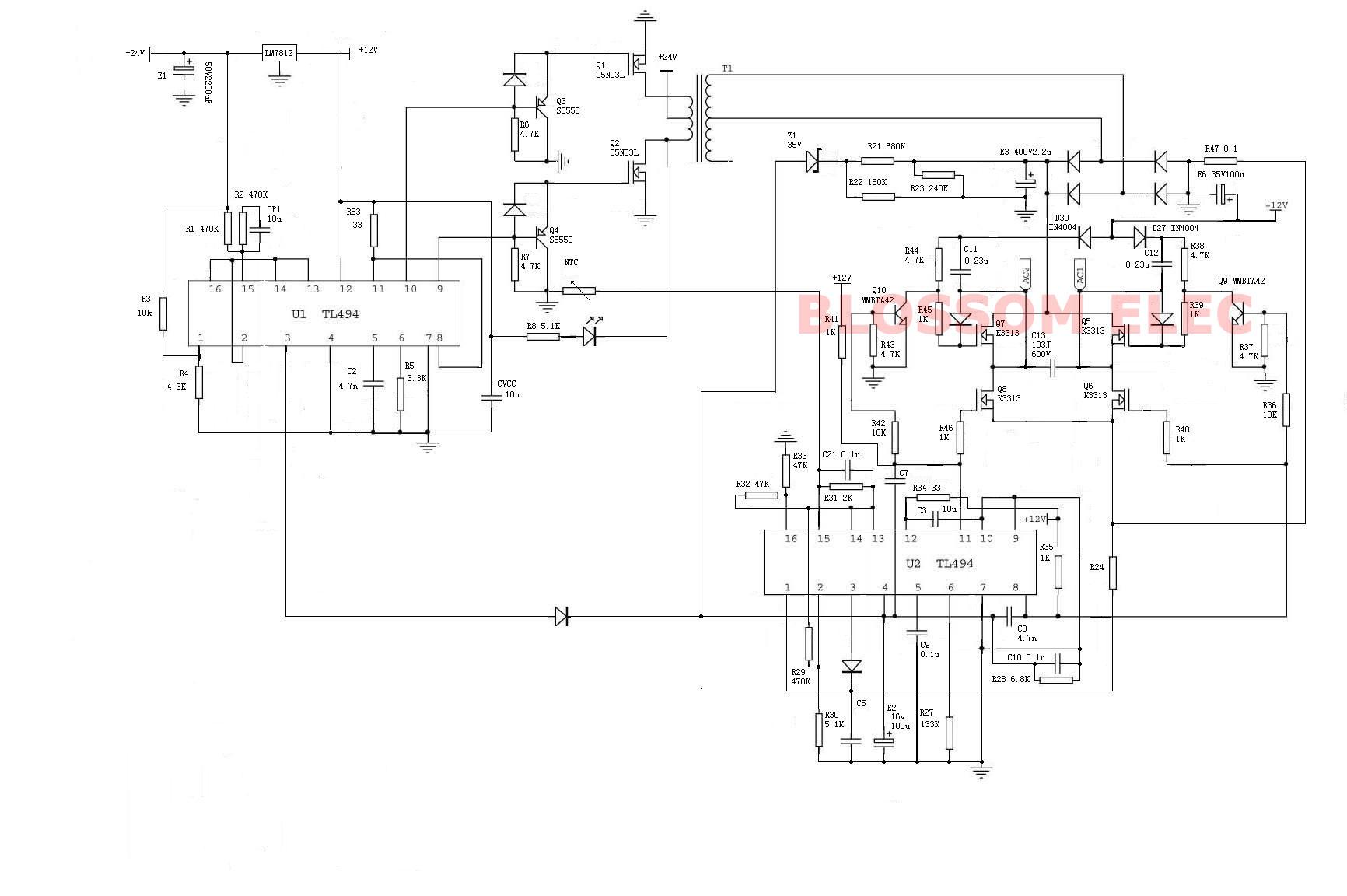
Power H Bridge Inverter Circuit : Sinewave Power Inverter With Floating H Bridge Auxiliary Switches Sw Download Scientific Diagram : The above circuit i got from replies from edaboard.. The idea is best suited for inverter applications for efficiently converting a low power dc to mains level ac. If this voltage needs to be boosted from the dc source, it can be accomplished After rectification 311 volt output from dc/dc to converter is fed to h bridge. From π + φ to 2 π, v0 < 0 and i0 < 0 then switches s3, s4 conducts For now, i put a large 200ns dead time between the pwm signals.
From φ to π, v0 > 0 and i0 > 0 then switches s1, s2 conducts case2: Circuit diagram of the half bridge inverter is as shown in below figure. H bridge is used to generate positive and negative cycle of ac voltage. The idea is best suited for inverter applications for efficiently converting a low power dc to mains level ac. After rectification 311 volt output from dc/dc to converter is fed to h bridge.
Power Circuit Diagram Of A Single Phase Full Bridge Inverter Download Scientific Diagram from www.researchgate.net With this inverter, you can power up various electronic appliances like tv, fan etc. Featured snippet from the web. The switch s 1 will conduct when the voltage is positive and current is negative, switch s 2 will conduct when. But when i try to combine them the ir2110 always blows up. Inverter h bridge mosfet circuit. This type of inverter requires two power electronics switches (mosfet). For now, i put a large 200ns dead time between the pwm signals. As shown in circuit diagram, input dc voltage is vdc = 100 v.
From π + φ to 2 π, v0 < 0 and i0 < 0 then switches s3, s4 conducts
High power h bridge circuits are used for controlling high power dc motors and they are also used in inverters. Circuit diagram of the half bridge inverter is as shown in below figure. The circuit of a full bridge inverter consists of 4 diodes and 4 controlled switches as shown below. The switch s 1 will conduct when the voltage is positive and current is negative, switch s 2 will conduct when. With this inverter, you can power up various electronic appliances like tv, fan etc. Sine wave inverters will power devices with more accuracy, less power loss, and less heat generation. Sbreaks were used in order to simulate the switching characteristics of near ideal transistors. Full bridge inverter wave form conduction angle. N1, n2, n3, n4 not gates from the ic 4049 are arranged as a voltage doubler circuit, which generates about 20 volts from the available 12v supply. The aim of the inverter circuit is to convert 12vdc to 220vac, now to achieve this, we have to first convert 12vdc to 12vac first followed by 12vac to 220vac using a step up transformer. Where each switch is connected to diodes d 1 and d 2 parallelly. After rectification 311 volt output from dc/dc to converter is fed to h bridge. Inverter h bridge mosfet circuit.
Große auswahl an netzteilen auf lager. The number of dc sources are two so the output voltage of the cascaded multilevel inverter is vdc = vdc1 + vdc2 5. Full bridge inverter wave form conduction angle. An input voltage (vin) of 10 v was chosen arbitrarily for the simulation. Control switch can be any electronic switch i.e.
Full Bridge Inverter An Overview Sciencedirect Topics from ars.els-cdn.com H bridge is used to generate positive and negative cycle of ac voltage. The aim of the inverter circuit is to convert 12vdc to 220vac, now to achieve this, we have to first convert 12vdc to 12vac first followed by 12vac to 220vac using a step up transformer. I have used irf840 in my final year project hybrid pure sine wave inveter. Conduction angle of each switch and each diode can be determined using the waveform of v0 and i0. H bridge inverter power stage with passives. I had created a thread there on how can i drive a 2 pin primary transformer with h bridge configuration with my sg3524 pwm circuit. 36 thoughts on simple 12v to 230vac inverter circuit mosfet. But when i want to use the full bridge, the problem occurs.
I have built the circuit attached herein on a pcb.
With this inverter, you can power up various electronic appliances like tv, fan etc. Große auswahl an netzteilen auf lager. Featured snippet from the web. Control switch can be any electronic switch i.e. Ein weltweit führendes unternehmen für elektronikkomponenten und dienstleistungen! Sbreaks were used in order to simulate the switching characteristics of near ideal transistors. Full bridge inverter wave form conduction angle. This type of inverter requires two power electronics switches (mosfet). Circuit diagram of the half bridge inverter is as shown in below figure. I had created a thread there on how can i drive a 2 pin primary transformer with h bridge configuration with my sg3524 pwm circuit. The components required for conversion are two times more than that used in single phase half bridge inverters. I have built the circuit attached herein on a pcb. The purpose of a dc/ac power inverter is typically to take dc power supplied by a battery, such as a 12 volt car battery, and transform it into a 120 volt ac power source operating at 60 hz, emulating the power available at an ordinary household electrical outlet.
These circuits are often used in robotics and other applications to allow dc motors to run forwards or backwards. I got many replies to use dedicated driver ics, suggestions to use floating high side gate driver, etc. H bridge inverter power stage with passives circuits diy here we look at some variations for my power mosfet h bridge. 36 thoughts on simple 12v to 230vac inverter circuit mosfet. An input voltage (vin) of 10 v was chosen arbitrarily for the simulation.
Solved Dc To Ac Inverter H Bridge Forum For Electronics from images.elektroda.net After rectification 311 volt output from dc/dc to converter is fed to h bridge. Sine wave inverters will power devices with more accuracy, less power loss, and less heat generation. H bridge is used to generate positive and negative cycle of ac voltage. Featured snippet from the web. As shown in circuit diagram, input dc voltage is vdc = 100 v. I have built the circuit attached herein on a pcb. Where rl is the resistive load, v s /2 is the voltage source, s 1 and s 2 are the two switches, i 0 is the current. The switch s 1 will conduct when the voltage is positive and current is negative, switch s 2 will conduct when.
H bridge is used to generate positive and negative cycle of ac voltage.
From 0 to φ, v0 > 0 and i0 < 0 then diodes d1, d2 conducts case3: H bridge switches selection also depend on power rating of power inverter. With this inverter, you can power up various electronic appliances like tv, fan etc. Where each switch is connected to diodes d 1 and d 2 parallelly. Mosfet, bjt, ijbt, or thyristor, etc. Circuit diagram of the half bridge inverter is as shown in below figure. Full bridge inverter wave form conduction angle. Ein weltweit führendes unternehmen für elektronikkomponenten und dienstleistungen! The number of dc sources are two so the output voltage of the cascaded multilevel inverter is vdc = vdc1 + vdc2 5. These circuits are often used in robotics and other applications to allow dc motors to run forwards or backwards. High power h bridge circuits are used for controlling high power dc motors and they are also used in inverters. 36 thoughts on simple 12v to 230vac inverter circuit mosfet. I have used irf840 in my final year project hybrid pure sine wave inveter.